
Threaded Flanges are a type of pipe flange commonly used for connecting pipes in low-pressure, non-critical applications. They are designed with threads on the inside of the flange bore, which allows the flange to be screwed onto a pipe without the need for welding. This feature makes threaded flanges ideal for systems where welding is not feasible, such as in explosive atmospheres or with materials that are sensitive to high temperatures.
These flanges are manufactured in accordance with industry standards such as ANSI B16.5, with pressure classes ranging from Class 150 to Class 2500, and are available in a variety of materials, including stainless steel, carbon steel, and alloy steel. Threaded flanges are offered in different facing types, such as raised face (RF) or flat face (FF), to suit different installation requirements. They are typically used in applications where frequent disassembly or maintenance is required, like plumbing systems, compressed air lines, and industrial processing plants.
Threaded flanges are available in a range of sizes from NPS 1/2" to NPS 24". Their key advantage is that they allow for easy installation without specialized tools, reducing downtime and installation costs. However, they are recommended primarily for low-pressure and low-temperature applications since threads are more prone to leaks under high pressure compared to welded joints. These flanges are widely used in industries such as petrochemical, oil & gas, water treatment, and chemical processing.
Specification of Threaded Flange
| ASME B16.5 Threaded Flanges Size Chart | 1/2" (15 NB) to 48" (1200NB) DN10~DN5000 |
|---|---|
| Threaded pipe flange Standards | ANSI/ASME B16.5, B16.47 Series A & B, B16.48, BS4504, BS 10, EN-1092, DIN, ANSI Flanges, ASME Flanges, BS Flanges, DIN Flanges, EN Flanges, GOST Flange, ASME/ANSI B16.5/16.36/16.47A/16.47B, MSS S44, ISO70051, JISB2220, BS1560-3.1, API7S-15, API7S-43, API605, EN1092 |
| JIS | 5K, 10 K, 16 K 20 K, 30 K, 40 K, 63 K Screwed Flanges |
| UNI | 6Bar 10Bar 16Bar 25Bar 40Bar Threaded pipe flange |
| Screwed Flanges Pressure Calculation in DIN | 6Bar 10Bar 16Bar 25Bar 40Bar / PN6 PN10 PN16 PN25 PN40, PN64 Bsp Threaded Flange |
| Bsp Threaded Flange Pressure Rating ANSI | Class 150 LBS, 300 LBS, 600 LBS, 900 LBS, 1500 LBS, 2500 LBS Pn16 Threaded Flange |
| EN | 6Bar 10Bar 16Bar 25Bar 40Bar Reducing Threaded Flange |
| Most common types of Carbon Steel Threaded Flange | Forged / Threaded / Screwed / Plate |
| Production technique |
|
| Test Certificates | EN 10204/3.1B Raw Materials Certificate 100% Radiography Test Report Third Party Inspection Report, etc |
| Coating | Oil Black Paint, Anti-rust Paint, Zinc Plated, Yellow Transparent, Cold and Hot Dip Galvanized Threaded Flanges |
| Connect Type/ Flange Face Type | Raised Face (RF), Ring Type Joint (RTJ), Flat Face (FF), Large Male-Female (LMF), Lap-Joint Face (LJF), Small Male-Female (SMF), Small Tongue, Large Tongue & Groove, Groove |
| Special design |
As per your drawing AS, ANSI, BS, DIN and JIS |
| Test | Direct-reading Spectrograph, Hydrostatic testing machine, X-ray detector, UI trasonic flaw detector, Magnetic particle detector |
| Equipment | Press machine, Bending machine, Pushing Machine, electric bevelling machine, Sand-blasting machine etc |
| Origin | Indian / West Europe / Japan / USA / Korean |
| Threaded pipe flange Uses & application |
|
| Manufacturer of |
ANSI DIN, GOST, JIS, UNI, BS, AS2129, AWWA, EN, SABS, NFE etc.
|
| Export to | Ireland, Singapore, Saudi Arabia, Spain, Dubai, Indonesia, Ukraine, India, Iran, Canada, USA, Brazil, Peru, Thailand, Korea, Egypt, Oman, etc |
| Material Test Certificates (MTC) as per EN 10204 3.1 and EN 10204 3.2, Test Certificates certifying NACE MR0103, NACE MR0175 | |
Material of Threaded Flanges
| Carbon Steel Pn16 Threaded Flange |
|
| Austenitic Stainless Steel Square Threaded Flange |
|
| Alloy Steel High-Temp Screwed Flanges |
|
| Alloy Steel Low-Temp Reducing Threaded Flange |
|
| Nickel Alloy Bsp Threaded Flange |
|
| Titanium Reducing Threaded Flange |
|
Threaded Flange Types
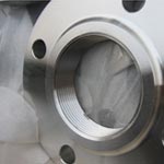
AWWA C207 Class d threaded flange adapter
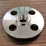
Forged Threaded Male & Female Flange
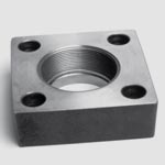
EN 1092 1 Square Threaded Flange
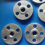
Stainless Steel Threaded Flange
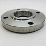
Threaded Flanges PN16
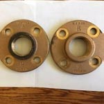
Brass Threaded Pipe Flange
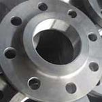
ASTM A182 F316 Reducing Threaded Flange
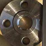
ASME B16.5 Threaded Flange
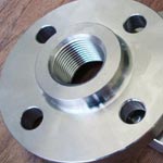
ANSI B16.5 Screwed Pipe Flange
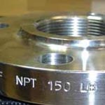
ASTM A694 F42 npt threaded Flanges
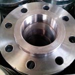
ASME B16.47 Series b NPT Threaded Flanges
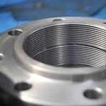
MSS SP-44 threaded lap joint flange
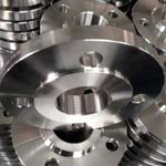
Class 300 Threaded Flange Dimensions
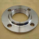
ASME B16.47 Series a Slip On Threaded Flange
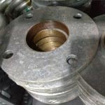
ASME B16.5 Screwed Flange
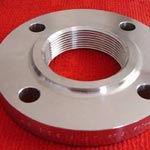
ANSI 150 Threaded Flange Dimensions
Stainless Steel Threaded Flange Dimensions
| Pipe Size
(NPS) |
Outside Diameter of Flange
A |
Diameter of Raised Face
B |
Thickness of Flange
C |
Diameter of Hub at Base
J |
Length of Hub
L |
Minimum Thread Length
N |
Number of Bolt Holes
|
Approx. Weight
(Lbs.) |
|---|---|---|---|---|---|---|---|---|
| 1/2 | 3 1/2 | 1 3/8 | 7/16 | 1 3/16 | 5/8 | 5/8 | 4 | 2 |
| 3/4 | 3 7/8 | 1 11/16 | 1/2 | 1 1/2 | 5/8 | 5/8 | 4 | 2 |
| 1 | 4 1/4 | 2 | 9/16 | 1 15/16 | 11/16 | 11/16 | 4 | 2 |
| 1 1/4 | 4 5/8 | 2 1/2 | 5/8 | 2 5/16 | 13/16 | 13/16 | 4 | 3 |
| 1 1/2 | 5 | 2 7/8 | 11/16 | 2 9/16 | 7/8 | 7/8 | 4 | 3 |
| 2 | 6 | 3 5/8 | 3/4 | 3 7/16 | 1 | 1 | 4 | 5 |
| 2 1/2 | 7 | 4 1/8 | 7/8 | 3 9/16 | 1 1/8 | 1 1/8 | 4 | 7 |
| 3 | 7 1/2 | 5 | 15/16 | 4 1/4 | 1 3/16 | 1 3/16 | 4 | 8 |
| 3 1/2 | 8 1/2 | 5 1/2 | 15/16 | 4 13/16 | 1 1/4 | 1 1/4 | 8 | 11 |
| 4 | 9 | 6 3/16 | 15/16 | 5 5/16 | 1 5/16 | 1 5/16 | 8 | 13 |
| 5 | 10 | 7 5/16 | 15/16 | 6 7/16 | 1 7/16 | 1 7/16 | 8 | 15 |
| 6 | 11 | 8 1/2 | 1 | 7 9/16 | 1 9/16 | 1 9/16 | 8 | 19 |
| 8 | 13 1/2 | 10 5/8 | 1 1/8 | 9 11/16 | 1 3/4 | 1 3/4 | 8 | 30 |
| 10 | 16 | 12 3/4 | 1 3/16 | 12 | 1 15/16 | 1 15/16 | 12 | 43 |
| 12 | 19 | 15 | 1 1/4 | 14 3/8 | 2 3/16 | 2 3/16 | 12 | 64 |
| 14 | 21 | 16 1/4 | 1 3/8 | 15 3/4 | 2 1/4 | 2 1/4 | 12 | 85 |
| 16 | 23 1/2 | 18 1/2 | 1 7/16 | 18 | 2 1/2 | 2 1/2 | 16 | 93 |
| 18 | 25 | 21 | 1 9/16 | 19 7/8 | 2 11/16 | 2 11/16 | 16 | 120 |
| 20 | 27 1/2 | 23 | 1 11/16 | 22 | 2 7/8 | 2 7/8 | 20 | 155 |
| 22 | 29 1/2 | 25 1/4 | 1 13/16 | 24 | 3 1/8 | 3 1/8 | 20 | 159 |
| 24 | 32 | 27 1/4 | 1 7/8 | 26 1/8 | 3 1/4 | 3 1/4 | 20 | 210 |
ANSI 150 Threaded Flange Dimensions
| Drilling | ||||||||
|---|---|---|---|---|---|---|---|---|
| Nominal Bore Threaded Flanges | Dia.(D) | Thick.(E) | Dia.(F) | Dia.(B) | Height1(H) | Nbr | Holes | Dia.(C) |
| 1/2″ | 90 | 9.6 | 35.05 | 30 | 14 | 4 | 15.87 | 60.3 |
| 3/4″ | 100 | 11.2 | 42.92 | 38 | 14 | 4 | 15.87 | 69.9 |
| 1″ | 110 | 12.7 | 50.80 | 49 | 16 | 4 | 15.87 | 79.4 |
| 1 1/4″ | 115 | 14.3 | 63.50 | 59 | 19 | 4 | 15.87 | 88.9 |
| 1 1/2″ | 125 | 15.9 | 73.15 | 65 | 21 | 4 | 15.87 | 98.4 |
| 2″ | 150 | 17.5 | 91.94 | 78 | 24 | 4 | 19.05 | 120.7 |
| 2 1/2″ | 180 | 20.7 | 104.65 | 90 | 27 | 4 | 19.05 | 139.7 |
| 3″ | 190 | 22.3 | 127.00 | 108 | 29 | 4 | 19.05 | 152.4 |
| 3 1/2″ | 215 | 22.3 | 139.70 | 122 | 30 | 8 | 19.05 | 177.8 |
| 4″ | 230 | 22.3 | 157.22 | 135 | 32 | 8 | 19.05 | 190.5 |
| 5″ | 255 | 22.3 | 185.67 | 164 | 35 | 8 | 22.22 | 215.9 |
| 6″ | 280 | 23.9 | 215.90 | 192 | 38 | 8 | 22.22 | 241.3 |
| 8″ | 345 | 27.0 | 269.75 | 246 | 43 | 8 | 22.22 | 298.5 |
| 10″ | 405 | 28.6 | 323.85 | 305 | 48 | 12 | 25.40 | 362.0 |
| 12″ | 485 | 30.2 | 381.00 | 365 | 54 | 12 | 25.40 | 431.8 |
| 14″ | 535 | 33.4 | 412.75 | 400 | 56 | 12 | 28.57 | 476.3 |
| 16″ | 595 | 35.0 | 469.90 | 457 | 62 | 16 | 28.57 | 539.8 |
| 18″ | 635 | 38.1 | 533.40 | 505 | 67 | 16 | 31.75 | 577.9 |
| 20″ | 700 | 41.3 | 584.20 | 559 | 71 | 20 | 31.75 | 635.0 |
| 24″ | 815 | 46.1 | 692.15 | 663 | 81 | 20 | 34.92 | 749.3 |
Carbon Steel Threaded Flanges Class 300 Lbs Dimensions
| Drilling | |||||||||
|---|---|---|---|---|---|---|---|---|---|
| Nominal Bore Threaded Flanges | Dia.(D) | Thick.(E) | Dia.(F) | Dia.(B) | Dia.(A) | Height1(H) | Nbr | Holes | Dia.(C) |
| 1/2″ | 95 | 12.7 | 35.05 | 38 | 23.6 | 21 | 4 | 15.87 | 66.7 |
| 3/4″ | 115 | 14.3 | 42.92 | 48 | 29.0 | 24 | 4 | 19.05 | 82.6 |
| 1″ | 125 | 15.9 | 50.80 | 54 | 35.8 | 25 | 4 | 19.05 | 88.9 |
| 1 1/4″ | 135 | 17.5 | 63.50 | 64 | 44.4 | 25 | 4 | 19.05 | 98.4 |
| 1 1/2″ | 155 | 19.1 | 73.15 | 70 | 50.3 | 29 | 8 | 22.22 | 114.3 |
| 2″ | 165 | 20.7 | 91.94 | 84 | 63.5 | 32 | 8 | 19.05 | 127.0 |
| 2 1/2″ | 190 | 23.9 | 104.65 | 100 | 76.2 | 37 | 8 | 22.22 | 149.2 |
| 3″ | 210 | 27.0 | 127.00 | 117 | 92.2 | 41 | 8 | 22.22 | 168.3 |
| 3 1/2″ | 230 | 28.6 | 139.70 | 133 | 104.9 | 43 | 8 | 22.22 | 184.2 |
| 4″ | 255 | 30.2 | 157.22 | 146 | 117.6 | 46 | 8 | 22.22 | 200.0 |
| 5″ | 280 | 33.4 | 185.67 | 178 | 144.4 | 49 | 8 | 22.22 | 235.0 |
| 6″ | 320 | 35.0 | 215.90 | 206 | 171.4 | 51 | 12 | 22.22 | 269.9 |
| 8″ | 380 | 39.7 | 269.75 | 260 | 222.2 | 60 | 12 | 25.40 | 330.2 |
| 10″ | 445 | 46.1 | 323.85 | 321 | 276.2 | 65 | 16 | 28.57 | 387.4 |
| 12″ | 520 | 49.3 | 381.00 | 375 | 328.6 | 71 | 16 | 31.75 | 450.8 |
| 14″ | 585 | 52.4 | 412.75 | 425 | 360.4 | 75 | 20 | 31.75 | 514.4 |
| 16″ | 650 | 55.6 | 469.90 | 483 | 411.2 | 81 | 20 | 34.92 | 571.5 |
| 18″ | 710 | 58.8 | 533.40 | 533 | 462.0 | 87 | 24 | 34.92 | 628.6 |
| 20″ | 775 | 62.0 | 584.20 | 587 | 512.8 | 94 | 24 | 34.92 | 685.8 |
| 24″ | 915 | 68.3 | 692.15 | 702 | 614.4 | 105 | 24 | 41.27 | 812.8 |
Dimensions of Class 600 Threaded Flange
| Drilling | |||||||||
|---|---|---|---|---|---|---|---|---|---|
| Nominal Bore Threaded Flanges | Dia.(D) | Thick.(E) | Dia.(F) | Dia.(B) | Dia.(A) | Height1(H) | Nbr | Holes | Dia.(C) |
| 1/2″ | 95 | 14.3 | 35.05 | 38 | 23.6 | 22 | 4 | 15.87 | 66.7 |
| 3/4″ | 115 | 15.9 | 42.92 | 48 | 29.0 | 25 | 4 | 19.05 | 82.6 |
| 1″ | 125 | 17.5 | 50.80 | 54 | 35.8 | 27 | 4 | 19.05 | 88.9 |
| 1 1/4″ | 135 | 20.7 | 63.50 | 64 | 44.4 | 29 | 4 | 19.05 | 98.4 |
| 1 1/2″ | 155 | 22.3 | 73.15 | 70 | 50.6 | 32 | 4 | 22.22 | 114.3 |
| 2″ | 165 | 25.4 | 91.94 | 84 | 63.5 | 37 | 8 | 19.05 | 127.0 |
| 2 1/2″ | 190 | 28.6 | 104.65 | 100 | 76.2 | 41 | 8 | 22.22 | 149.2 |
| 3″ | 210 | 31.8 | 127.00 | 117 | 92.2 | 46 | 8 | 22.22 | 168.3 |
| 3 1/2″ | 230 | 35.0 | 139.70 | 133 | 104.9 | 49 | 8 | 25.40 | 184.2 |
| 4″ | 275 | 38.1 | 157.22 | 152 | 117.6 | 54 | 8 | 25.40 | 215.9 |
| 5″ | 330 | 44.5 | 185.67 | 189 | 144.4 | 60 | 8 | 28.57 | 266.7 |
| 6″ | 355 | 47.7 | 215.90 | 222 | 171.4 | 67 | 12 | 31.75 | 292.1 |
| 8″ | 420 | 55.6 | 269.75 | 273 | 222.2 | 76 | 12 | 31.75 | 349.2 |
| 10″ | 510 | 63.5 | 323.85 | 343 | 276.2 | 86 | 16 | 34.92 | 431.8 |
| 12″ | 560 | 66.7 | 381.00 | 400 | 328.6 | 92 | 20 | 34.92 | 489.0 |
| 14″ | 605 | 69.9 | 412.75 | 432 | 360.4 | 94 | 20 | 38.10 | 527.0 |
| 16″ | 685 | 76.2 | 469.90 | 495 | 411.2 | 106 | 20 | 41.27 | 603.2 |
| 18″ | 745 | 82.6 | 533.40 | 546 | 462.0 | 117 | 20 | 44.45 | 654.0 |
| 20″ | 815 | 88.9 | 584.20 | 610 | 512.8 | 127 | 24 | 44.45 | 723.9 |
| 24″ | 940 | 101.6 | 692.15 | 718 | 614.4 | 140 | 24 | 47.62 | 838.2 |
Threaded Flange Pressure Ratings
Maximum allowable non-shock pressure (psig) and temperature ratings for threaded flange ansi b16.5 and flanged fittings according the American National Standard ANSI B16.5 – 1988.
| Maximum Allowable non-shock Pressure (psig) | |||||||
|---|---|---|---|---|---|---|---|
| Temperature (oF) |
Pressure Class (lb) | ||||||
| 150 | 300 | 400 | 600 | 900 | 1500 | 2500 | |
| Hydrostatic Test Pressure (psig) | |||||||
| 450 | 1125 | 1500 | 2225 | 3350 | 5575 | 9275 | |
| -20 to 100 | 290 | 750 | 1000 | 1500 | 2250 | 3750 | 6250 |
| 200 | 260 | 750 | 1000 | 1500 | 2250 | 3750 | 6250 |
| 300 | 230 | 730 | 970 | 1455 | 2185 | 3640 | 6070 |
| 400 | 200 | 705 | 940 | 1405 | 2110 | 3520 | 5865 |
| 500 | 170 | 665 | 885 | 1330 | 1995 | 3325 | 5540 |
| 600 | 140 | 605 | 805 | 1210 | 1815 | 3025 | 5040 |
| 650 | 125 | 590 | 785 | 1175 | 1765 | 2940 | 4905 |
| 700 | 110 | 555 | 740 | 1110 | 1665 | 2775 | 4630 |
| 750 | 95 | 505 | 675 | 1015 | 1520 | 2535 | 4230 |
| 800 | 80 | 410 | 550 | 825 | 1235 | 2055 | 3430 |
| 850 | 65 | 320 | 425 | 640 | 955 | 1595 | 2655 |
| 900 | 50 | 225 | 295 | 445 | 670 | 1115 | 1855 |
| 950 | 35 | 135 | 185 | 275 | 410 | 685 | 1145 |
| 1000 | 20 | 85 | 115 | 170 | 255 | 430 | 715 |
Threaded Flanges PN16 Tolerances
| Outside Diameter ≤ 24 = 1.6 mm | > 24 = ± 3.2 mm |
Inside Diameter Within Limits on Boring Gauge |
|---|---|
| Diameter of Contact Face 1.6 mm Raised Face = ± 0.8 mm 6.35 mm Raised Face, Tongue & Groove / Male-Female = ± 0.4 mm |
Drilling Bolt Circle = 1.6 mm | Bolt Hole Spacing = ± 0.8 mm Eccentricity of Bolt Circle with Respect to Facing ≤ 2½ = 0.8 mm max. | ≥ 3 = 1.6 mm max. |
| Outside Diameter of Hub ≤ 12 = + 2.4 mm / - 1.6 mm | ≥ 14 = ± 3.2 mm |
Diameter of Counterbore Same as forInside Diameter |
| Thickness ≤ 18 = + 3.2 mm / - 0 | ≥ 20 = + 4.8 mm / - 0 |
Length thru Hub ≤ 18 = + 3.2 mm / - 0.8 mm | ≥ 20 = + 4.8 mm / - 1.6 mm |


